Wavelength Calibration
Published reference
Further information may be found in Wolff et al. 2014 “Gemini Planet Imager Observational Calibrations IV: Wavelength Calibration and Flexure Correction for the Integral Field Spectrograph”
Observed Effect and Relevant Physics:
To perform GPI’s exoplanet characterization science goals requires a wavelength precision of ~1%. However, the uniformity of the datacube is greatly increased with a better quality calibration. Performing a robust, high-accuracy wavelength calibration with GPI has been one of the primary challenges of the pipeline development. Similar to other near-IR spectrographs, GPI uses the well calibrated emission lines of a Xenon or Argon lamp (Argon requires more computation time to fit blended lines, but the GCAL Ar lamp is several times brighter than the Xe lamp). The current accuracy of the wavelength calibration is below 0.5% for all bands. The new calibration based on forward modeling provides wavelength information accurate to within several hundredths of a pixel in all bands.
Using Wavelength Calibrations in the GPI Pipeline
Most data reduction recipes for raw GPI data will begin by loading a wavelength calibration using the pipeline primitive Load Wavelength Calibration. Typically the calibration is obtained automatically from the Calibration Database based on the closest-in-time wavelength calibration file. There are no significant user-selectable options for this step to be concerned with.
If the wavelength solution was taken at a very different time than the science data in question, it is likely that internal flexure in the IFS results in an offset between the two. This has to be compensated for using the Update Spot Shifts for Flexure primitive. See IFS Flexure for further information.
Creating Calibrations:
Calibration DB File Type: Wavelength Solution Cal File
File Suffix: wavecal
Generate with Recipe: “Wavelength Solution” or “Wavelength Solution 2D”
Take a series of arc lamp exposures (multiple exposures to increase S/N). Reduce these using one of the two wavelength solution recipes discussed below. This will create a references datacube (“wavecal file”) that provides the starting x and y positions, the wavelength at those positions, the wavelength dispersion, and the tilt angle for each lenslet spectrum. This wavecal may then be used to extract full spectral data cubes from science data.
The Xenon arc lamp spectrum has more cleanly separated emission lines, but with our updated algorithms we now believe the pipeline can derive good wavelength calibrations from either Xe or Ar. The GCAL Ar lamp is 3-10x brighter depending on wavelength so the integration times are favorable. In general, Gemini instrument scientists will ensure proper calibration data are taken for wavecals.
There are three different recipes for creating wavelength calibrations:
- “Wavelength Solution” will bootstrap a wavelength solution from scratch using centroids measured for the arc lamp emssion lines. It is somewhat fragile and in particular is sensitive to any residual hot pixels in your data, and the generated wavecal is not of the highest quality. This recipe should only be used if you’re setting up a copy of the pipeline from scratch with no existing wavecal files.
- “Wavelength Solution 2D” on the other hand fits a 2D forward model of the dispersed spectrum to each lenslet and minimizes the chi squared to derive a more accurate wavecal. It yields better results but requires that you already have at least one prior wavecal already to use as a starting guess for the optimization. This is the right recipe to use the vast majority of the time.
- “Quick Wavelength Solution” is designed to work on lower signal to noise arc lamp data taken contemporary with science data to correct for flexure within the IFS. I combines multiple lenslet spectra to fit an x and y position offset to an existing wavelength calibration file. This primitive is explained in more detail in the IFS Flexure section.
Note
The Wavelength Solution 2D recipe is computationally intensive, and will take tens of minutes to run on typical machines. The parallelized mode does not work with IDL Virtual Machine.
Things to Watch Out For
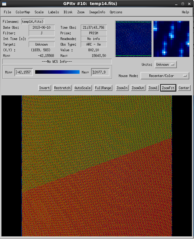
Performing the wavelength calibrations are quite simple but ensuring that the determination was successful does require examination of the solution in GPItv (see the Displaying GPI Wavelength Calibration feature documentation). As the Gaussian fitting routines that determine the locations of the of spots are sensitive to bad pixels, it is recommended that a recent badpixel mask is used. The following figure shows the successful completion of a wavelength calibration.
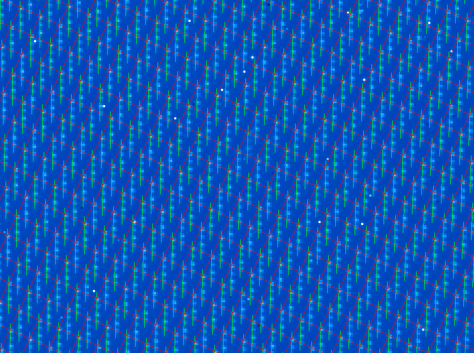
If we zoom in on this figure, you can see two sets of grid lines. A successful determination of the calibration will show a clean grid of centroids (intersection of the red lines) with identical length dispersion axes (shown as green lines). The grid and dispersion lines appear uniform in the image below.
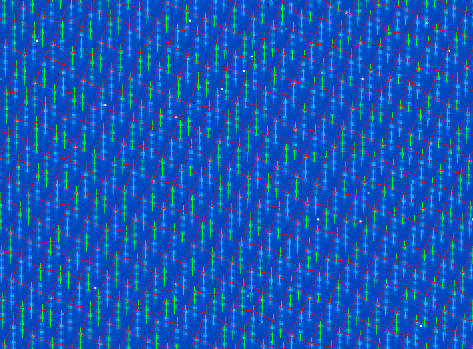
The following image shows a zoomed in region of a bad wavelength calibration. Note that the grid has become uneven. In this case, the S/N was not high enough and bad pixels adversely effect the fit.
If you do experience a failed wavelength calibration, first check to make sure the correct dark and badpixel mask were used. The wavelength solution 2D primitive relies on a reference wavelength solution. If this file is not clean, this will cause errors in the final wavecal. The pipeline will automatically choose the most recent reference wavelength calibration files, but the user can manual choose a file by editing the CalibrationFile primitive keyword in the Recipe Editor. One may also change the interpolation type of the bad-pixel interpolation.
Relevant GPI team members
Schuyler Wolff, Zack Draper, Marshall Perrin