IFS Flexure
See also
Further information may be found in Wolff et al. 2014 “Gemini Planet Imager Observational Calibrations IV: Wavelength Calibration and Flexure Correction for the Integral Field Spectrograph” and also in Ingraham et al. 2014 “Gemini Planet Imager Observational Calibrations III: Empirical Measurement Methods and Applications of High-Resolution Microlens PSFs”
Observed Effect and Relevant Physics:
The positions of the individual spectra formed from each microlens are subject to gravitationally induced flexure that affects optical components between the microlens array and science detector on the IFS optical bench. Under normal observational procedure, as the instrument moves in elevation, the flexure is observed to follow standard hysteresis curves with amplitudes of ~0.5 pixels.
When the instrument is moved outside of it’s normal observing range, being above ~80 degrees in elevation or when the cassegrain rotator is in use due to ongoing observations with other instruments, a non-repeatable and unpredictable flexure component is introduced. Although the cause of this has not been confirmed, it is believed to result from an optic or it’s mount in the IFS exhibiting micron-level shifts when moved into non-standard positions. Due to the sensitive IFS alignment and the inaccessibility of the suspected optic, it has been decided to compensate for the non-repeatable flexure component in the data reduction software.
Currently, the data reduction pipeline (DRP) corrects for the repeatable component of flexure by adding offsets to the positions of the microspectra that were determined when measuring their wavelength solution (zenith). This is accomplished using a lookup table and the Update Spot Shifts for Flexure primitive. In order to compensate for the non-repeatable component of the flexure, an arclamp image (normally Argon) is taken at either the beginning or end of the observing sequence. This provides a zero point offset to the hysteresis curves. How to implement this offset is discussed below.
It is worth noting here that the IFS flexure also impedes our ability to preform a flat field correction because the spectra fall on different pixels throughout the observation, more details can be found in the Lenslet flat field and Detector flat fielding sections.
Using Flexure Shifts in the GPI Pipeline
Note
The quick start tutorial gives a quick example on how to apply flexure offets to wavelength calibrations, we recommend at least reading the applicable sections of the tutorial prior to this section.
When reducing science data, the standard recipes, Spectral Science contain the Update spot shifts for flexure primitive. This primitive allows the user to select between a manual flexure shift, default flexure shifts from a lookup table, no shifts, and the BandShift mode. If manual flexure shifts are chosen, the x and y shifts are controlled by the manual_dx and manual_dy keywords. The Lookup method requires a calibration file with a ‘shifts’ extension. This table lists the shifts in x and y as a function of elevation. This method will compensate for the repeatable flexure offsets discussed above. The BandPass mode was developed to take advantage of the derived shifts from the quick H band arc lamp images taken at the same elevation as science targets across all bands. It uses the x and y positions from the most recent wavelength calibration and extrapolates to the bandpass of the science data. This mode is not extensively tested. We recommend beginning with the lookup table option.
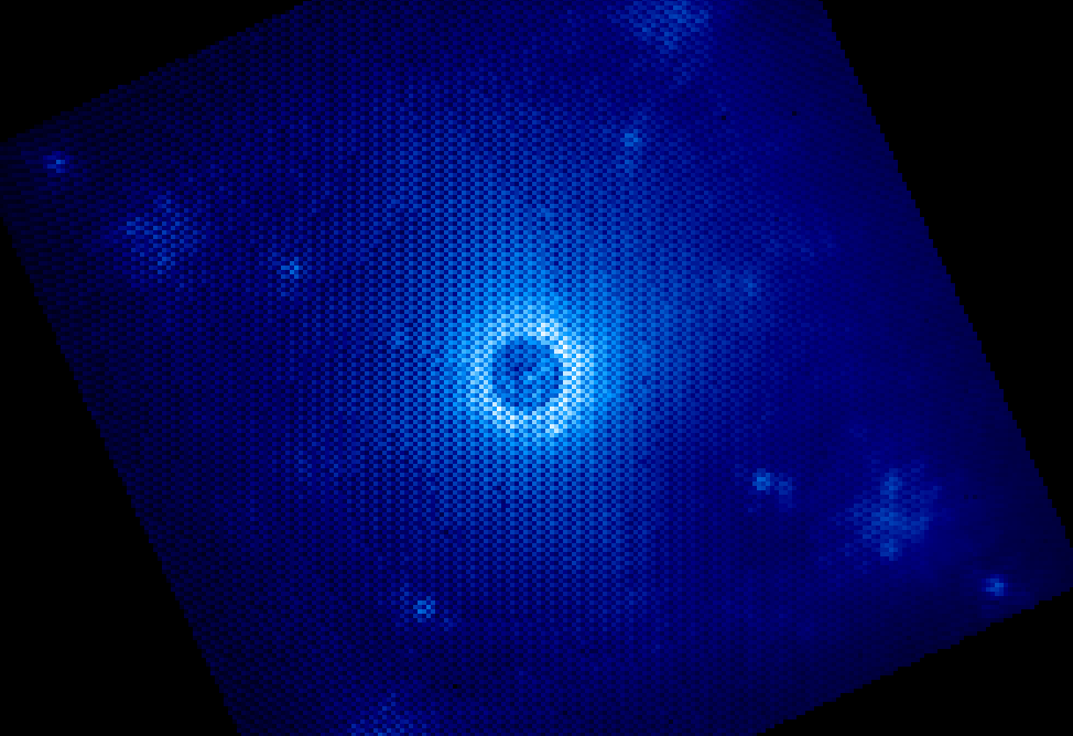
If your datacube was reduced with the wrong flexure solution, the datacube will exhibit a checkerboard pattern. The figure below shows a slice of a datacube that used incorrect flexure shifts (1.5 pixels off in both x and y).
In this case, it is likely necessary to input a manual flexure since a non-repeatable flexure component has resulted in an offset to the standard flexure curves. To determine the necessary shifts, you should open the raw science frame and overplot the wavelength solution. For information on how to do this see Displaying GPI Wavelength Calibration feature. The user may change the position of the overplotted lenslet locations until they line up with the data. Sub pixel position accuracy is possible by eye. Once the wavelength solution is plotted over the Raw data, the user can click and drag the wavelength solution grid using the ‘Move Wavecal Grid’ Mouse Mode. The offsets will be displayed in red to the nearest pixel.
Note
The x direction shifts are easy to determine by eye, but the ability to determine the shifts in the y-direction can be dependent on the spectral features of your target.
It has become stardard practice at Gemini South to take short exposure arc lamp images contemporary with all GPI science targets for flexure compensation. The user should then run the Quick Wavelength Solution recipe template (found under the Calibration recipe menu), on the Argon lamp image taken with the data. The user should input the approximate solutions (rounded to the nearest integer) into the xoffset and yoffset parameters into the Quick Wavelength Solution Update primitive. When running the recipe, one must be careful to ensure the proper wavelength calibration is grabbed from the database (check the output in the pipeline xterm). If the wrong one is selected, then you can manually choose the correct one using the Choose Calibration File button. By default, a new wavelength calibration corresponding to the wavelength of the Argon arc taken with the data is created. Printed on the pipeline xterm window will also be the calculated offsets and uncertainties from the master wavelength calibration.
Note
The offsets calculated will apply to ALL master wavelength calibrations since they are all taken with the telescope at zenith.
The user should verify that these offsets make sense relative to the offsets they determined by eye. It is also recommended that the user examine the solution, this can be done by setting the display parameter to a value greater than 1. The user can sometimes increase the precision by decreasing the spacing parameter at the cost of computing time. Expanding the boxsizex or boxsizey parameter may also help in finding the proper solution.
Things to watch out for:
The Quick Wavelength Solution Update will output offsets regardless of their validity. It is very important the user checks them!
If the user reduces their data using the wavelength solution created using a Quick Wavelength solution, the flexure offsets as the target moves in elevation will be applied if the Lookup method is enabled. For short observations, the amount of elevation change will be very small and no flexure compensation will be required.
Relevant GPI team members
Patrick Ingraham, Marshall Perrin, Schuyler Wolff