| Basic Specifications |
Models |
5101 / UJ - Atomic Four 5111 / UJS - Atomic Four
Stevedore (Atomic Four configured for the Canadian market
- power limited to 18 hp with intake manifold
restriction)
5102 / UJR - Atomic
Four with Paragon reduction gearbox mounted on
transmission
5112 / UJSR -
Atomic Four Stevedore (Atomic Four configured for the
Canadian market - power limited to 18 hp with intake
manifold restriction) with Paragon reduction gearbox
mounted on transmission
5103 / UJVD -
Atomic Four with Walter V drive gearbox mounted on
transmission
5113 / UJSVD -
Atomic Four Stevedore (Atomic Four configured for the
Canadian market - power limited to 18 hp with intake
manifold restriction) with Walter V drive gearbox
mounted on transmission
|
| |
Type |
Vertical, in line, 4 cycle, L (flat)
head |
| |
Serial Number Locations |
Pre 1969: stamped on right, forward
side of block above starter motor Post 1968: stamped on block above
flywheel housing, and on an id tag glued to top of
manifold
Post 1977: stamped
on block above flywheel housing, on an id tag glued to
top of manifold, and on an id tag glued to front of the
flywheel housing cover
|
| |
Universal Foundry
("UF") Casting
Part Numbers |
block: UJ-1 (595369)
head: UJ-2
pan: UJ-4
marine gear housing: UJ-5 (121571)
camshaft: UJ-8
connecting rod: UJ-10
main bearing cap, front: UJ-15
oil pump cover: UJ-17
camshaft timing gear: UJ-27
rear thrust bearing outer plate: UJ-90
idler gear: UJ-96
V-drive manifold end cap: UJ-410
flywheel
housing:
flywheel cover:
manifold:
head to manifold coolant tube - pre 1969:
thermostat housing:
block plate - pre 1969:
valve cover - pre 1969:
rear thrust bearing
inner plate:
flywheel:
crankshaft:
crankshaft timing gear:
crankshaft drive gear:
oil pump gear:
auxiliary drive pulley (early pulleys made for engines with generators
had thinner sheave sides: than later pulleys intended for use with
alternators):
auxiliary drive housing:
|
| |
|
|
| Dimensions |
Cylinders |
4 |
| |
Nominal bore |
65 mm / 2.562 in |
| |
Nominal stroke |
79 mm / 3.125 in |
| |
Nominal engine displacement
(swept volume) |
1056 cc (1 litre) / 64.44 cu in |
| |
Nominal stroke / bore ratio |
1.22 (under square) |
| |
Nominal compression ratio |
6.3:1 |
| |
Nominal peak (maximum) piston
speed |
1825.8 ft / min |
| |
Nominal piston to head
clearance |
? in |
| |
Nominal piston to crank
clearance |
? in |
| |
Nominal rod ratio |
1.917 |
| |
Piston pin offset |
0.00" |
| |
Nominal deck height |
8.993 in |
| |
Nominal connecting rod length |
6.0 in |
| |
Nominal crank throw |
1.565 in |
| |
Nominal
piston deck clearance |
0 in |
| |
Nominal
piston compression height |
1.428
in |
| |
Weight |
UJ (direct drive): 310 lb
UJR (reduction drive): 330 lb
UJVD (V drive): 335 lb |
| |
Nominal peak (maximum) power
output |
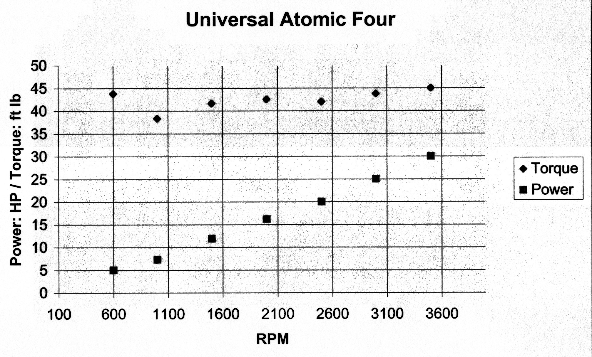
Standard Atomic Four: 30 hp @ 3,500 rpm
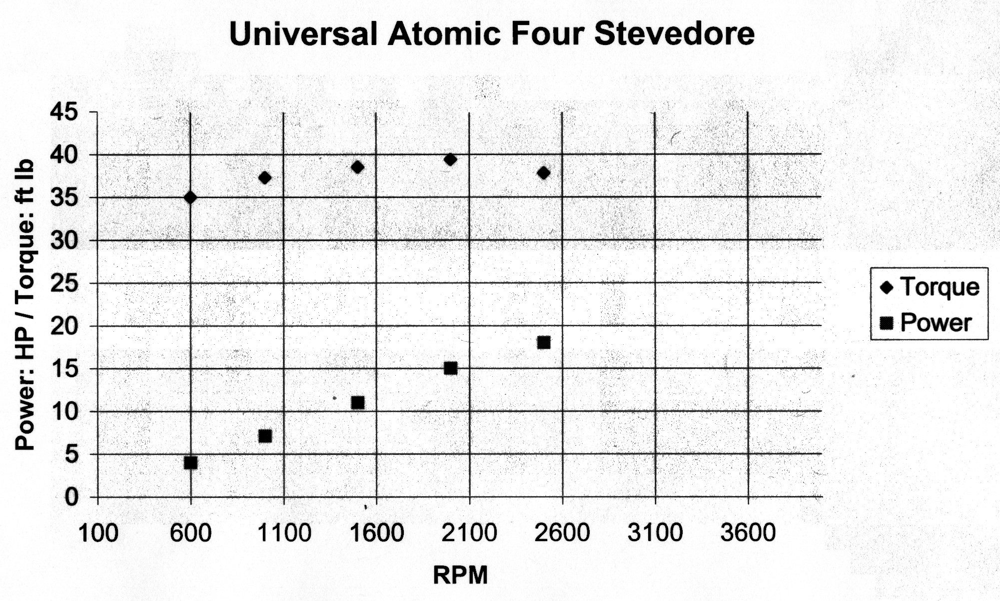
Atomic Four Stevedore with intake restrictor: 18 hp @ 2,500 rpm |
| |
Nominal peak (maximum) Brake
Mean Effective Pressure (BMP) |
103 psi |
| |
Nominal rated torque at peak (maximum) rpm |
Standard Atomic Four: 45 lb ft @ 3,500 rpm
Atomic Four Stevedore with intake restrictor: 37 lb ft @ 2,500 rpm |
| |
Nominal peak (maximum) rated torque |
Standard Atomic Four: 45 lb ft @ 3,500 rpm (maximum
rpm)
Atomic Four Stevedore with intake restrictor: 39.5 lb ft @ 2,125 rpm
(85% of maximum rpm) |
| |
Nominal torque rise |
Standard Atomic Four: 0%
Atomic Four Stevedore with intake restrictor: 7% |
| |
Nominal peak (maximum)
specific output
(power/piston crown area) |
Standard Atomic Four: 1.46 hp / sq in
Atomic Four Stevedore with intake restrictor: .877 hp / sq in |
| |
Nominal weight / power ratio (direct drive
model) |
Standard Atomic Four: 10.33 lb / hp
Atomic Four Stevedore with intake restrictor: 17.22 lb / hp |
| |
Nominal weight / displacement
ratio (direct drive models) |
4.81 lb / cu in |
| |
Nominal peak (maximum) power
/ displacement ratio |
Standard Atomic Four: .47 hp / cu in
Atomic Four Stevedore with intake restrictor: .28 hp / cu in |
| |
Torque / RPM / Power
(standard Atomic Four) |
|
| |
Torque / RPM / Power
(Atomic Four Stevedore with intake restrictor) |
|
| |
|
|
| Components |
Cylinder block |
Cast en-block with marine chrome
nickel iron alloy crankcase & full length water
jackets |
| |
Cylinder head |
Marine chrome nickel iron alloy detachable
head |
| |
Crankshaft |
2 main bearing, high carbon steel,
fully counterweighted, statically and dynamically
balanced, uses insert (Vandervell shell type) bearings |
| |
Connecting Rods |
Drop forged, high carbon steel,
floating piston pin, insert bearings, new style rods with
thicker I beam section: weight = 480 g / 17 oz |
| |
Pistons |
Cast aluminum, flat-top, 3 ring - 2
compression rings and 1 oil control ring, full floating piston
pin retained by steel circlips, 0 pin offset, expansion slot on non-thrust skirt |
| |
Oil pan |
Marine chrome nickel iron alloy, one piece,
partially baffled marine type, integral engine mounts |
| |
Manifold |
Marine chrome nickel iron alloy water jacketed exhaust and intake
manifold in one casting. Separate exhaust flange tapped 1
1/4 in NPT bolts to manifold with two 3/8" NC cap
screws or studs at exhaust opening at rear of manifold. V
drive models use same manifold with cap over rear opening
and front opening machined for exhaust flange so that
engine can be mounted facing backwards, as required for
use of V drive. |
| |
Exhaust pipe attachment |
1 1/4 in NPT female pipe thread in removeable flat
flange held on by 2 3/8" NC studs or cap screws |
| |
Lubrication |
Full pressure to mains, connecting
rod big ends, idler gear stud, camshaft bearings,
transmission sun & planet gear assembly
Marine type fine brass mesh oil pump pickup screen
surrounding pickup to retain oil in rough seas and
prevent oil pump ingesting air, exterior oil pressure
adjustment |
| |
Water jacket cover |
Removeable mild steel block water
jacket plate (stainless steel plates available from
after-market suppliers but not recommended, they
encourage galvanic corrosion of the block instead of the
cover plate... for the same reason do not use stainless
steel nuts and bolts) |
| |
Cooling system |
Constant flow, 2 stage thermostat,
rubber impellor water pump (later models) |
| |
Thermostat upper plate height |
Original OEM Holley 3 spring: closed
(cold) 8.3 mm / .325 in / open (hot) 15.9 mm / .625 in
Replacement OEM Westerbeke single spring: closed (cold)
5.1 mm / .2 in / open (hot) 20.3 mm / .8 in |
| |
Thermostat housing bypass
boss depth |
10.2 mm / .4 in |
| |
Mechanical fuel pump pushrod
size |
39.37 mm / 1.550 in long x 9.53 mm /
.375 in diameter |
| |
Marine gear (transmission) |
Paragon: combined engine /
marine gear lubrication system with marine gear running
in engine oil, sun and planet gear type, forward uses
multiple plate clutch pack with over-centre pressure and
lock, reverse uses clutch band on sun gear housing, the
carrier gear assembly is pressure lubricated via a port
on the crankshaft rear main bearing, the rear thrust
bearing at the drive flange is splash lubricated via a
bearing shield which meters the oil to and from the
bearing / rear seal.
propeller shaft flange: 3 hole,
3/8" NF cap screws, 1.375" radius holes @ 120°, flat
surface (no centring ring)
|
| |
Reduction Gear (optional) |
Single step, internal helical and
pinion type, Paragon #RO-20, 2.04:1 ratio standard, 3.01:1 ratio
optional
propeller shaft flange: 4 hole,
3/8" NF cap screws, 1.63" radius holes @ 90°, 2 5/8"
diameter centring ring
|
| |
V drive (optional) |
Single step, internal gear type, Walter, 24° V angle, 1.00:1 ratio standard...
1.29:1 / 1.67:1 / 2.0:1 ratios optional
propeller shaft flange: 3 hole,
5/16 NC cap screws, ?" radius holes @ 120°, flat surface (no centring
ring)
|
| |
Carburetor |
Updraft Zenith marine non-drip type
carburetor, upturned air horn with flame arrester screen:
1949 - 1968: Zenith type 61, cast-iron (adjustable main
jet)
1969 - 1984: Zenith Bendix type 68-7 - 13355, aluminum
(fixed main jet) |
| |
Starting System |
1948: - 1967: Prestolite starter, 12
volt DC Prestolite solenoid
1967 - 1984: Delco Remy 1107679 starter, 12 volt DC Delco
solenoid |
| |
Charging System |
1948: - 1967 - dual foot saddle mount
6 (later 12) volt Prestolite marine generator, mechanical
generato-mounted voltage regulator
1967 - 1984: single 2" foot mount 12 volt DC 35 amp
Motorola (optional 50 amp Leece-Neville or Motorola)
marine alternator, transistorized alternator-mounted
voltage regulator |
| |
Ignition System |
1948 - 1967: Prestolite 1Gw60032E1X
distributor, Prestolite coil
1967 - 1984: Delco Remy #1112446 - 2G11/6C16/3HI8
distributor, Delco Remy 070FLX 12 volt coil |
| |
Propeller rotation |
Right hand (clockwise facing the rear
of the propeller) (all models) |
| |
Propeller shaft / coupling inner diameter |
Direct Drive: ¾ in, 7/8 in, 1 in
Reduction Drive: 1 in, 1 1/8 in
V Drive: 7/8 in, 1 in |
| |
Propeller Size
Note: propeller fitted to direct drive and V drive-1:1 ratio
models must allow the engine to
reach at least 1,800 rpm during hull speed / full
throttle testing. Propellers fitted to reduction drive and V
drive-reduction ratio models must allow the engine to reach 3,300 rpm
during hull speed/full throttle testing |
2 blade (sailboat standard)
Direct drive: 11 in x 7 in, 12 in x 6 in (most common size), 13 in x 5 in
2:1 reduction or V drive: 12 in x 11 in, 13 in x 10 in, 14 in x 9 in, 15 in x
8 in, 16 in x 7 in (most common size)3 blade (cabin cruiser &
workboat standard - recommended for use on sailboats in
areas with severe currents, winds, tides)
Direct drive: 10 in x 6 in (most common size), 11 in x 5 in
2:1 ratio reduction or V drive: 12 in x 10 in, 13 in x 9 in, 14 in x 8
in (most common size), 15 in x 6 in
Note: + / - 1 in
change in pitch or diameter changes maximum rpm by
approximately - / + 100 rpm
|
| |
Crankshaft rotation |
Counter-clockwise viewed from flywheel end
Clockwise viewed from
rear of engine/reduction box/V drive output shaft (ie all models use a
right hand prop) |
| |
Fuel |
Original specification was
"standard 92 - 94 octane gasoline", later
revised to "regular 90 - 94 octane" (when the
specifications were written all gasoline contained lead,
which was used to raise the octane rating and extend
valve seat life). Modern "Regular" 87 or 89
octane non-leaded gasoline is OK as long as the
compression is below 120 psi and the ignition timing is
set by adjusting distributor at full cruise speed to give
maximum tachometer rpm. Octane booster & lead
additive is not recommended or necessary. |
| |
|
|
| Dimensions |
Maximum operating angle |
15° |
| |
Maximum rotation angle |
25° |
| |
Length overall |
UJ: 26 ¾ in, UJR: 31 15/16 in, UJVD:
35 13/16 in |
| |
Height above crankshaft
centreline |
13.125 in |
| |
Maximum width |
18.250 in |
| |
Offset – crankshaft to
propeller shaft |
UJ: 0 in
UJR: 1.042 in
UJVD: na |
| |
Base depth below centreline |
6 in |
| |
Firing order (#1 cylinder:
flywheel end) |
1 2 4 3 |
| |
Valve timing |
Inlet valve opens: 5 BTDC
Inlet valve closes: 50 ABDC
Exhaust valve opens: 45 BBDC
Exhaust valve closes: 10 ATDC |
| |
Valve guide dimensions |
1.5 in long x .502 in outer diameter
x .315 in inner diameter |
| |
Valve guide bore in block |
.500 in inner diameter |
| |
Valve length |
3.685 in |
| |
Intake valve head diameter |
1.500 in |
| |
Exhaust valve head diameter |
1.030 in |
| |
Valve spring outer diameter |
1949 – 1967: .785 in
1966 – 1967: .800 in
1968 – 1984: .810 in
1995 - present: .800 in |
| |
Valve spring inner diameter |
1949 – present: .62 in |
| |
Valve spring free length |
1949 – 1967: 1.825 in (coil
bound at .76 in)
1966 – 1967: 1.925 in (coil bound at .80 in)
1968 – 1984: 2.075 in (coil bound at .81 in)
1995 - present: 2.2 in (coil bound at .80 in) |
| |
Valve spring pressure |
compressed to 1 in: 50 - 60 psi |
| |
Valve spring coil direction |
left hand |
| |
Valve tappets |
Diameter
all years: .810"Length
19? – 19?: 1.725 in overall / 1.575 in bucket
19? – 19?: 1.975 in overall / 1.595 in bucket
19? – 19?: 1.910 in overall / 1.725 in bucket
19? – 19?: 1.975 in overall / 1.790 in bucket
Note: When
installing replacement new or used tappets check to make
sure tappet is long enough to allow clearance to grip
flat section with a open-end wrench so the valve
clearance adjustment can be accomplished.
|
| |
Compression |
90 psi – 125 psi, optimum 104
psi |
| |
Alternator drive ratio
(through PTO gear & V belt pulley) |
1.75:1 (1 turn of engine crankshaft =
1 ¾ turn alternator) |
| |
Flywheel ring gear &
housing dimensions |
1949 – 1967 (Prestolite
starter): ring gear OD / flywheel housing ID 11 in 1968 – 1984 (Delco
starter): ring gear OD / flywheel housing ID 11.5 in
|
| |
Fuel consumption |
Approximately 4 litres/hour (1 US
gal/hour) @ 2,000 rpm under load depending on boat size
& winds/currents |
| |
Primary fuel
filter/water separator recommendation |
Filter mesh size & type rating:
10 micron with water separator section & metal bowl
(ie Racor 320R-RAC-02) [Note: do not use 2 micron filter elements in
primary water separator filters... they are too fine and can cause
fuel pump failure]
Minimum Flow Rating: 15 litre / hour
|
| |
Mechanical fuel pump |
AC Delco mechanical rubber diaphragm
type, maximum pressure 3.0 psi
Auxiliary sediment bowl with internal mesh filter |
| |
Electric fuel pump |
Facet 574A, 12 volts, maximum
pressure 4.0 psi
Internal mesh filter accessible by removing cam lock
bottom cap
In-line fuse/breaker 10 amp
Should be fitted with oil pressure safety switch (Hobbs
76576 - 10 n.o.) to stop pump if engine stalls or
ignition switch left in "on" position |
| |
Pipe / Hose Sizes |
Exhaust flange: 1 1/4 in NPT - 1 1/2
in or 1 /5/8 in hose
Water pump inlet: 3/8 in NPT - 1/2 in or 5/8 in rigid (wire reinforced) hose
Water pump outlet: 3/8 in NPT - 1/2 in hose
Fuel pump connection: 1/8 in NPT - 5/16 in OD copper
pipe, double flared or 1/4 in ID hose (alcohol
compatible) |
| |
Oil
dipstick Sizes |
Direct
drive (DD): full mark - 6 3/8 in, low mark - 6 3/4 in
(direct drive old style dipstick top notch = new style dipstick full
mark)
V drive (VD): full mark - 6 3/4
in, low mark - 7 1/4 in
|
| |
|
|
| |
|
|
| Design Changes |
Engine Specification Updates |
circa 1949: Serial #?
Zenith series 61-M2AE7 cast iron carburetor with
adjustable main jet
single metal head gasket
Dole thermostat
Auto-lite ignition
Fairbanks Morse magneto (optional)
Auto-lite 6 volt starter
Auto-lite 6 volt generator
Prestolite distributor (1Gw60032E1X)
bronze gear water pump
old style heat exchanger kit (optional)
5 unit control panel with mechanical tachometer,
mechanical oil pressure gauge, mechanical water
temperature gaugecirca 1962: Serial #?
Jabsco rubber impellor water pump (available as a
replacement)
Prestolite 12 volt starter
Leece Neville 12 volt alternator (optional)
circa 1963:
Serial #?
Prestolite 12 volt generator
Auto-lite 15 amp 12 volt generator (optional)
Delco Remy 24 amp 12 volt generator (optional)
Prestolite 35 amp 12 volt alternator (optional)
Prestolite 40 amp 12 volt alternator (optional)
circa 1964:
Serial #?
Ongaro - Teleflex electric control panel with electric
tachometer (optional), electric oil pressure gauge,
electric water temperature gauge
circa 1964:
Serial #?
single metal head gasket replaced with 2 composition gaskets
circa 1965:
Serial #?
"old" Sherwood (7 end cover screws) rubber
impellor water pump
circa 1967:
Serial #79476
new style cylinder head with integral thermostat housing
Holley thermostat
new style Sendure heat exchanger kit (optional)
Medallion 6 unit control panel with electric tachometer
(optional), electric oil pressure gauge, electric water
temperature gauge
circa 1967:
Serial #170509
Zenith series 68-7 13355 alumininum alloy
carburetor with fixed main jet
Delco Remy distributor (#1112446 - 2G11/6C16/3HI8)
Delco Remy 070FLX 12 volt coil
Delco Remy 1107679 starter and new ring gear to fit
larger flywheel housing to fit new ring gear
Motorola 35 amp 12 volt alternator (Motorola 51 amp 12
volt alternator optional)
Oberdorfer model 202M3 rubber impellor water pump (fitted
to most engines)
circa 1967:
Serial #171514
external valve chamber oil line no longer fitted
circa 1968:
Serial #174340
Oberdorfer model 202M3 water pump standard
circa 1969:
Serial #174802
new style valves (often stamped "Eaton" or
"Etn", but new OEM valves now come without markings)
circa 1969:
Serial #175503
new transmission housing, oil fill moved to
front
circa 1970:
Serial #176500
valve guide inner diameter revised to .3145 -
.3150 in (new valve guide/valve stem clearance
specification of .003 - .004 in to prevent valves
sticking in guides)
circa 1972:
Serial #178801
Paragon marine gear updated with new outer plate
combined with pressure plate, and new wider metric gear
carrier ball bearing
circa 1975:
Serial #192787
new style deep flywheel housing and flat sheet
metal cover
circa 197?:
Serial #?
new style electric instrument panel (electric
tachometer optional)
circa 1979:
Serial #202987
mechanical fuel pump replaced with Facet
electric fuel pump and low oil pressure shut-off switch
circa 1980:
Serial #20?
production stopped (sales continued to 1984)
|
| |
|
|
| Wear Limits / Machining Specs |
Bore |
to fit OEM Universal/Westerbeke "Mahle" pistons
Std size: 2.5625 in (+ - .0005 in)
.010 in oversize: 2.5725 in (+ - .0005 in)
.020 in oversize: 2.5825 in (+ - .0005 in)
to fit EGGE Pistons
same as OEM pistons above... EGGE pistons are designed to fit standard
bore sizes
|
| |
Maximum cylinder bore ovality |
maximum .002 in |
| |
Maximum cylinder bore taper |
.008 in |
| |
|
|
| |
Piston skirt clearance |
OEM Universal/Westerbeke "Mahle" pistons - all bore sizes
.0015 in (+ - .0005) [feeler blade to 5 lb pull]
"EGGE" pistons - all
bore sizes
.003 in (+ - .0005) [feeler blade to 5 lb
pull]
|
| |
Piston ring gap |
.007 in - .015 in (check near bottom
of bore in area of minimum wear/minimum bore diameter...
use a piston to push ring down into position for gap
measurement) |
| |
Piston ring installation |
OEM Westerbeke - Standard Bore Size
(OEM #287761 - STD)
1. No longer uses an inner expander ring with the oil
ring
2. Top 2 rings are the same... both install with the
inner bevel upOEM Westerbeke - Oversize Bore Sizes
(OEM #287873 - .010 in, #287874 - .020 in, #287875 - .030
in)
1. Uses an inner expander ring with the oil ring
2. Top ring installs with the inner bevel up
3. Second ring installs with the outer lip down
Hastings or Ertel
rings - Standard Bore Size (6520 - STD):
1. Uses an inner expander ring with the oil ring...
ensure it is fitted beneath the oil ring with the spring
end gaps over the oil drain slot in the bottom of the
piston oil ring land (located over the vertical expansion
slot in the piston skirt)
2. Top ring installs with the inner bevel up
3. Second ring installs with the outer lip down
Hastings or Ertel
rings - Oversize Bore Sizes (6520 - .010 in, 6520 - .020
in):
1. Uses an inner expander ring with the oil ring...
ensure it is fitted beneath the oil ring with the spring
end gaps over the oil drain slot in the bottom of the
piston oil ring land (located over the vertical expansion
slot in the piston skirt)
2. Top 2 rings both install with the inner bevel up
Note: Install both
types of rings with gaps staggered about 120 degrees
around piston. Do not locate any gaps in the middle of
the thrust side (the thrust side of the piston has no
vertical expansion slot in the piston skirt)
|
| |
Piston ring side clearance |
Top (compression): .0015 in - .003 in
Middle: .001 in - .0025 in
Bottom (oil): .001 in - .0025 in |
| |
|
|
| |
Connecting rod small end ID
(no bushing) |
.750 in |
| |
Piston pin diameter |
.6880 in |
| |
Piston pin rod bushing ID (installed &
honed) |
.6885 in - .6890 in |
| |
Piston pin clearance in rod
bushing |
.0005 in - .001 in |
| |
Piston pin clearance in
piston (light push fit) |
.0001 in - .0002 in |
| |
|
|
| |
Cylinder head, manifold, block head deck,
& block manifold deck surface roughness specification |
rotary broach: #125 RA (this is the OEM
surface roughness specification) / #139 RMS
surface grinder: #95 RA / #105 RMS
belt sander: #110 RA / #122 RMS
(Note: most automotive machine
shops grind Atomic Four heads, manifolds, blocks too
smooth... tell them you want a finish which feels slightly rough to the
finger-nail if they don't understand what #125 RA means)
|
| |
Cylinder bore honing finish |
OEM & Hastings rings - 45 degree crosshatch with
#20 RA / #25 RMS to #24 RA / 30 RMS finish (220 grit stones) |
| |
|
|
| |
Oil pump drive end play |
.001 in - .003 in |
| |
Oil pump gear backlash |
.003 in - .005 in |
| |
|
|
| |
Camshaft gear backlash |
.002 in - .004 in |
| |
Idler gear backlash |
.002 in - .004 in |
| |
Accessory gear backlash |
.002 in - .004 in |
| |
|
|
| |
Connecting rod big end side
play on crankshaft journal |
.004 in - .008 in |
| |
Crankshaft end play (at front
main bearing) |
.002 in - .003 in |
| |
|
|
| |
Valve face angle |
45° |
| |
Valve seat angle |
45° |
| |
Valve seat width |
1/32 in |
| |
Valve stem diameter |
.3115 in - .312 in |
| |
Valve stem / guide clearance |
cast iron guides: .003 in - .004 in
(OEM guides are cast iron)
bronze guides in fresh water cooled engines with 180
thermostat: .0035 - .0045 in |
| |
Valve guide internal diameter |
.3145 in - .3160 in to give correct clearance (see valve
stem/guide clearance above) |
| |
Valve spring installed length
- no cam lobe lift (intake & exhaust) |
1.19 in |
| |
Valve spring length - cam
lobe full lift (intake & exhaust) |
.94 in |
| |
Maximum cam lobe lift |
.239 in |
| |
|
|
| |
Front main bearing width: |
1.620 in |
| |
Crankshaft main bearing
journal |
Std: 1.9880 in, +.0005 in / -.0000 in
.010 in undersize: 1.9780, + .0005 in / - .0000 in
.020 in undersize: 1.9680, + .0005 in / - .0000 in
.030 in undersize: 1.9580, + .0005 in / - .0000 in
journal fillet radius:
1/16"
|
| |
Crankshaft rod bearing
journal |
Std: 1.5625 in, +.0000 in / .-.0005
in
.010 in undersize: 1.5525 in, + .0000 in / - .0005 in
.020 in undersize: 1.5425 in, + .0000 in / - .0005 in
.030 in undersize: 1.5325 in, + .0000 in / - .0005 in
journal fillet radius:
1/16"
|
| |
Crankshaft marine gear sun
& planet carrier bearing journal |
1.869 in, +.0005 in / .-.0000 in |
| |
Main bearing clearance |
.001 in - .0025 in |
| |
Rod bearing clearance |
.001 in - .0025 in |
| |
|
|
| |
Rod big end diameter (no
bearing shell) |
1.6685 in (maximum ovality .0003") |
| |
Rod side play on crankshaft
journal |
.004 in - .008 in |
| |
Rod installation |
Cylinder no stamped on rod big end
towards camshaft, #1 rod at front (flywheel end) on #1
piston, #2 rod second from front on #2 piston, etc |
| |
|
|
| |
Camshaft bearing journal |
1.3745 in, +.0005 in / -.0000 in |
| |
Camshaft bearing clearance |
.0015 in - .0025 in (line ream after
installation) |
| |
Camshaft bushing inner
diameter |
1.376 in – 1.377 in |
| |
|
|
| |
Valve tappet OD Valve tappet bore ID
Valve
tappet clearance
|
.8125 in .813 in
.0005 in
|
| |
|
|
| |
Piston installation |
Arrow on crown pointing to rear
(towards marine gear... yes - even though the piston is marked
"Front"), vertical expansion slot on skirt
facing away from camshaft, #1 piston at front (flywheel
end), #2 piston second from front, etc |
| |
Piston skirt diameter (bottom
of skirt near expansion slot at right angles to pin) Note: pistons are not round
when at room temperature because they are cam ground oval
so they expand to round when at engine running
temperature
|
Std: 2.560 in
.010 in oversize: 2.570 in
.020 in oversize: 2.580 in
.030 in oversize: 2.590 in |
| |
|
|
| |
Idler gear
|
idler gear bushing bore ID: .988 in |
| |
Idler gear shaft
Note: the idler gear shaft is held in the bore in block
with 2 allen set screws, one on top of the other. Remove the screws and
then use a special puller to withdraw the shaft |
idler shaft bore in block ID: .623 in
idler
shaft section pressed in block OD: .625 in
idler
shaft / section in block interference fit: -.002 in
idler gear
shaft OD: .875 in
|
| |
Idler gear bushing
|
bushing length: 1.0 in (grind flush with gear after
installation)
bushing OD before installation in gear: 1.002 in (bushing interference press fit
-.004 in)
installed bushing honed ID: .876 in
bushing to shaft clearance: .001 in
Note: to restore worn shaft grind undersize and hone new installed
bushing to .001 in clearance
|
| |
|
|
| |
Oil pump drive end play |
.001 in - .003 in |
| |
|
|
| |
Distance from top of cylinder
head spark plug thread to cylinder block deck |
.980 in - 1.175 in |
| |
Distance from bottom of spark
plug thread to cylinder head surface |
.480 in - .625 in, average
approximately .525 in |
| |
Cylinder head combustion
chamber volume with piston at TDC (including spark plug
hole) |
40 cc - 51 cc, average approximately
50 cc |
| |
Cylinder swept volume +
combustion chamber volume with piston at BDC (including
spark plug hole) |
313.5 cc, average approximately 314 cc |
| |
Maximum cylinder head warp |
.006 in |
| |
|
|
| |
|
|
| |
Valve spring compressed
length (full lift of camshaft lobe) |
?? in |
| |
Valve spring installed height
(with valve clearance) |
?? in |
| |
Valve spring pressure at full
lift |
60 psi |
| |
|
|
| |
Coil primary resistance |
Internal ballast type: 3 - 4 ohm
(standard 12 volt OEM Delco coil)
(Note: External ballast type (.5 - 1 ohm) is not
necessary or recommended. If fitted an external ballast
resistor (2 - 3 ohm) must also be installed in series.) |
| |
Starter solenoid current draw Starter winding
currrent draw
|
approximately 20 amps approximately 150 amps
|
| |
Starter
Battery Specification
|
12 volt,
minimum 90 - 125 ampere hours
|
| |
|
|
| |
Intake manifold vacuum |
Idle: 16 in Hg
2,000 rpm under load: 14 in Hg |
| |
Exhaust system back pressure
(measured at water injection point before water lock
muffler) |
2.5 psi / 5 in Hg / 68.5 in H2O - maximum at full load |
| |
Crankcase sump flow /
pressure (indicating piston ring and valve guide
combustion blow-by) |
New engine: approximately .25 cfm /
+0.5 in H2O / .036 in Hg / 0.018 psi at full speed / load
Worn engine: approximately .50 cfm / +1.0 in H2O / .072
in Hg / 0.036 psi at full speed / load
(Test pressure at valve cover
breather tube with oil fill tube breather cap removed and oil fill
tube blocked)
|
| |
Cylinder leak-down test (indicating piston ring/cylinder and valve/valve
seat leakage) |
New/rebuilt engine: 15% - 25%
New/rebuilt engine after break-in: 10% - 20%
Used engine in good condition: 25% - 50%
Worn engine: 50% - 100%
(Test leakdown with engine hot
and each cylinder at TDC)
|
| |
|
|
| |
Distributor rotor position @
TDC#1 (compression stroke) |
#1 terminal at 09:00 viewed from
front of engine (pointing to extrusion on distributor
plate which fits into slot in cap and is also at 09:00) |
| |
|
|
| Adjustments |
Nominal Ignition timing |
Stock Delco distributor:
Static: No advance = 0° BTDC /
Full advance = 12° BTDC*
Dynamic: < 1,000 rpm = 2° BTDC / 2,000 rpm = 6° BTDC / 3,000 rpm =
12° BTDC*
*Note: factory specifications state full advance is 17°, but testing
has shown the late model Delco distributor only advances 12° with
standard weights. That is a another good reason to set the timing by
slowly turning the distributor at full throttle while tied to the dock
or at top boat speed to get maximum engine rpm, rather than assuming
setting the timing to 0° BTDC with engine off will be accurate at
full cruise speed. (The other reason to set the timing at full speed
is because optimum timing varies with elevation, fuel octane rating,
compression ratio, and carburetor jet spec.)
Atomic Four Engine Service "Hi-Torque"
distributor (for direct drive engines only):
Dynamic: 1,000 rpm = 3° BTDC / 2,000 rpm = 6° BTDC -
maximum advance
|
| |
Valve tappet clearance |
Stock camshaft:
Intake: .008 in hot, .010 in cold
Exhaust: .010 in hot, .012 in cold
Atomic Four Engine Service/Colt
Cams "Hi-Torque" camshaft (for direct drive engines only):
Intake: .013 in hot, .015 in cold
Exhaust: .013 in hot, .015 in cold
|
| |
Distributor dwell |
Prestolite: 38°
Delco: 31° - 34° |
| |
Distributor points gap |
Prestolite: .018 in - .020 in
Delco: .025 in
magneto: .014 in - .018 in |
| |
Spark plug gap |
.035 in |
| |
Alternator belt tension |
3/8 in depression between centres,
pressing firmly with one finger (or the belt can just be turned
sideways) |
| |
Oil pressure relief valve |
35 psi at 2,000 rpm (or top cruising
speed) hot |
| |
Paragon marine gear forward
clutch pack |
approximately 30 - 50 ft lb torque on
shift shaft to force 3 pressure plate arms over bulge in
throw-out bearing |
| |
Paragon marine gear reverse
band |
with gear lever in neutral tighten
reverse band adjusting nut (holes in flats so a nail or
pick can be used as an adjusting tool) until output shaft
turns stiffly, then back off 1 - 2 rotations until shaft
turns freely |
| |
|
|
| |
|
|
| Lubricants |
Lubricating oil |
Quantity:
Depending on installation angle of
engine: 4 litres – 6 litres to full mark on dip stick (different dip sticks
for direct drive/reduction drive (UJ / UJRD) and V drive (UJVD).
Type:
non-synthetic
API rating:
SG or SG equivalent
Viscosity:
Average temperature under 10°C / 50°F: SAE 10-40
Average temperature over 10°C / 50°F: SAE 20-50
Atomic Four Engine Service
recommends only the motorcycle oils listed below in order to prevent
forward clutch slip while providing maximum engine protection and
optimum piston ring break-in. All the oils listed are available in
both 10-40 and 20-50 viscosities.
Castrol Grand Prix 4 Stroke Motorcycle Oil
Shell Advance SX4 Motorcycle Oil
Valvoline 4-Stroke Motorcycle Oil
Belray EXL Motorcycle Motor Oil
Pennzoil Motorcycle Motor Oil
Quaker State 4-Cycle Motorcycle Engine Oil
Notes: Never use ANY oil
additives. Do not switch brands.
|
| |
V Drive Oil |
.5 litre of SAE 80W90 hypoid oil (SAE
30 motor oil is also acceptable) |
| |
Water pump grease |
Waterproof grease (white lithium,
boat trailer wheel bearing grease, Lubriplate #115, or
any good quality water resistant grease)
Note: waterpump gease does not stop the pump from
leaking, it lubricates the bearing and seal. If the pump
leaks it needs to be rebuilt. |
| |
|
|
| Fastener Torque Note: Lubricate threads and
base of bolt head / nut with oil
|
Cylinder head stud nuts |
35 ft lb, 3 stages: 10 lb ft / 25 lb ft / 35 lb ft (apply engine oil to threads and bottom of nuts), use shop manual torquing diagram or torque
from centre of head out to ends. Retorque to 35 lb ft after 1 hour of running & cool-down. Note: install cylinder and
manifold studs into block with gasket cement or Loctite
"red", and coat sides of studs with Never-Seize
to prevent studs from seizing to head or manifold
|
| |
Connecting rod bolt nuts |
25 lb ft |
| |
Flywheel stud nuts |
35 lb ft |
| |
Main bearing stud nuts |
60 lb ft |
| |
Manifold stud nuts |
30 lb ft |
| |
Spark plugs |
30 lb ft (apply Never-Seize to
threads) |
| |
Valve cover cap screws |
20 lb in (with cork gasket) |
| |
Flywheel cover cap screws |
85 lb in |
| |
Idler Gear stud nut |
40 lb ft (use purple Loctite) |
| |
Oil pump cover screw |
7 lb ft (use
blue Loctite & new "high-collar" lock washers)) |
| |
Oil pan & block
5/16" cap screws |
14 lb ft |
| |
Transmission output shaft
flange nut |
60 lb ft (use blue Loctite & tab lock washer) |
| |
Crankshaft channeled gear
retaining bolt |
30 lb ft (use blue Loctite) |
| |
|
|
| Service Parts |
Spark plugs |
Specified plug:
Champion #871 (old number RJ8C)Recommended plug (slightly
hotter, helps stop plug sooting):
Champion #592 (old number RJ12C)
Other plugs used
(nominal Champion RJ8C equivalents):
NGK BR6S [not recommended - too cold]
Bosch W7EC, W7E, W9EC
AC R43, R44, R45
Autolite 304
Motocraft A3C, A3CU, A3X, A5X, A5CU
Denso W20S, W20SR-U, W20S-U
|
| |
Contact Breaker (points) |
Prestolite Distributor:
Echlin CS-709
Neihoff AL-533Delco
Distributor:
Delco D108P
Echlin CS788P
Niehoff DR6-HV
|
| |
Capacitor (Condenser) |
Prestolite Distributor:
Echlin AL38
Neihoff AL-38Delco
Distributor:
Delco D203
Echlin RR-176
Niehoff DR-22
Borg Warner G126
|
| |
Rotor |
Prestolite Distributor:
Echlin AL58
Neihoff AL-54Delco
Distributor:
Delco 423R
Echlin RR-182R
Niehoff DR-53A
Borg Warner G152
|
| |
Cap |
Prestolite Distributor:
Echlin AL91
Neihoff AL-79ADelco
Distributor:
Delco D322R
Echlin RR-181
Niehoff DR-74
|
| |
Coil |
for both Prestolite or Delco 12 volt Distributor:
Prestolite ?
Delco 070FLX
Echlin IC64
Niehoff DR-180 (standard)
Niehoff UN171 (epoxy heavy duty)
Standard UC15
Borg Warner E40BAP
UAP Napa IC64SB (this is probably a US part number...
Canadian UAP Napa part numbers are often differentSpecifications:
Primary Winding: 12 volt, internal resistor: 3 - 4 ohms
|
| |
Distributor |
Prestolite distributor:
IGW4116C / 60032E1XDelco distributor:
1112446 - 2G11/6C16/3HI8
|
| |
HT Leads (spark plug wires) |
Atomic Four Engine Service A4HTset Specifications:
Wire type: 7 mm high tension wire, carbon core resistor
type
Wire terminals & lengths (add 1 in to length when
cutting cable for custom wires to allow for stripping
insulation for terminal installation):
Coil/distributor lead: straight terminals, 9 in
#1 plug lead: straight distributor terminal/90 degree
plug terminal, 16.5 in
#2 plug lead: straight distributor terminal/90 degree
plug terminal, 13.5 in
#3 plug lead: straight distributor terminal/90 degree
plug terminal 10 in
#4 plug lead: straight distributor terminal/90 degree
plug terminal 8 in
|
| |
Generator/Alternator |
Prestolite 6 or 12 volt generator:
obsolete - substitute Delco alternator below:Motorola alternator:
Motorola MR12N4510 - type B (Voltage Regulator 8RG 2010A), 35 amps,
negative ground, internal voltage regulator, 3/8" pulley with a
diameter of 2 1/2"
Alternator upgrade:
Note: Maximum size which can be used with the existing
alternator drive pulley on the auxiliary drive is 90 amps. Some 90 amp
alternators charge so aggressively when the batteries are low that
they can cause the belt to slip and subsequently burn... 70 amps is a
safer size maximum. There isn't room to fit a 1/2" or double
pulley on the alternator and still clear the distributor, and because
the auxiliary drive alternator pulley is integral with the auxiliary
drive flange it is difficult to fit a different pulley on the
auxiliary drive anyway. Theoretically the alternator output should not
be larger than the maximum + reading of the ammeter, so the ammeter
will not be damaged when the alternator is generating maximum
amperage.
Specification: Specify a 12 volt
marine rated alternator (enclosed, sealed brushes)
with negative ground, integral solid state adjustable voltage regulator,
a clockwise (RH) fan, a single 2" foot mounting configuration, and a
3/8" pulley with a diameter of 2 1/2" or 3", rated at
35, 55, 70, or 90 amps.
|
| |
Starter |
OEM Prestolite:
MBG4129 (solenoid Wilson 60-01-6029)OEM Delco:
Delco 1107679
Wilson 91-01-3736 (starter drive Wilson 61-01-3455,
solenoid Wilson 60-01-3541)
Aqua Power 2826
Specifications:
12 volt (early models were 6 volt), negative ground,
marine type
Note: Prestolite
and Delco starters use different flywheel ring gears
|
| |
Alternator belt |
Dayco: 11A0635 (10A0635 also used)
Gates: 11A0635 (10A0635 also used) |
| |
Engine coolant hoses |
1/2" id automotive heater hose
& stainless steel gear clamps water pump outlet to block water
plate "T": 10.5 in
block water plate "T" to thermostat housing
inlet 90° fitting: 6.5 in
thermostat housing outlet to manifold inlet: 4.5 in
|
| |
Temperature Sensor (electric) |
SW 280ED-F
General Marine GEN26630
Aqua Power AP1943
Faria FAR90405Specification:
1/2" NPT, 12 volt to match control panel
temperature gauge(s)
|
| |
Oil Pressure Sensor
(electric) |
SW 279A
General Marine GEN24880
Faria FAR90512Specification:
1/8" NPT, 12 volt to match control panel oil
pressure gauge(s)
|
| |
Seawater pump belt (pump over
starter) |
Dayco: 11A770
Gates: 11A770 |
| |
OEM flange mounted water pump
- gear driven off PTO unit
(Used as sea water pump when engine is raw water
cooled with no heat exchanger. When heat exchanger is
fitted used as engine coolant pump, except when electric
pump is fitted, when it is used as sea water pump and
electric pump is used as an engine coolant pump.) |
After 1969 OEM pump was Oberdorfer
202M3 (2 US gal / minute, 15 psi max @ 1,000 rpm)
Cam thickness .105 in (half cam)Note: 202M3 is usually upgraded to
Oberdorfer 202M7 when rebuilt or replaced by installing
M7 cam. M7 was used on older diesels
Oberdorfer 202M7 (3 US gal / minute, 20 psi max @ 1,000
rpm)
Cam thickness: .150 in (full cam)
Impellor:
Oberdorfer B6593
West Marine 241044
Globe 815
Barco 815
Sherwood 295628
|
| |
Sea water pump used with heat
exchanger
(Belt driven off pulley on end of crankshaft at flywheel,
driven directly off end of crankshaft, belt driven using
alternator drive belt, or electric motor pump) |
Sherwood R30G / Jabsco 2620-1001 /
Oberdorfer 201M (or any pump with a continuous capacity
of 20 litres / minute @ 1,800 rpm and a rpm rating of at
least 3,000 rpm) water pump / crankshaft pulley ratio:
1:1
|
| |
Carburetor Jets |
1948 – 1968 Zenith 61-M2AE7:
main jet #24, Zenith C52-6-24 & adjustable main jet needle
assembly
idle jet #10, Zenith C55-6-10 (.019 in drill size)
well vent jet #22, Zenith C77-18-22 (.043 in drill size)
main discharge nozzle #50, Zenith C66-26-1-501969 – 1984 Zenith
Bendix 68-7 13355:
venturi #16
float needle & seat #25
main jet #21, Zenith C52-7-21 (.041 in drill size)
idle jet #12, Zenith C55-22-12 (.023 in drill size)
well vent jet #21, Zenith C77-18-21 (.041 in drill size)
main discharge nozzle #55, Zenith C66-114-4-55 (3 x .039
in drill size)
idle bleed hole, fixed plug (.039 in drill size)
|
| |
|
|
| Trouble-Shooting |
No-Start |
1. bad
coil - replace
2. bad points - gap/replace (grease distributor cam with tiny amount
of high melting point grease)
3. defective/corroded coil primary wire or ignition switch
4. blown head gasket - replace
5. water/dirt in fuel: carb/pump/tank - fuel tank condensation,
leaking tank filler cap (no "O" ring)
6. dead battery - accessories left on with engine off
7 dead battery - defective alternator
8. vapour lock in fuel line - relocate electric pump to below carb,
cool electric pump and fuel line
9. fouled plugs (especially NGK B6) - replace with Champion 592
|
| |
Low
power |
1.
running on 3 cylinders - repair
2. fuel starvation - repair
3. tight prop shaft packing gland - repair
4. blocked exhaust - repair
5. incorrect ignition timing - adjust
|
| |
Low
speed miss |
1.
incorrect carb adjustment - repair
2. water in fuel - repair
3. carb or manifold air leak - repair
4. bad condenser - replace
5. dirty/plugged flame arrester
6. flooding carb - check fuel pump pressure
|
| |
High
speed miss |
1.
fouled
spark plugs (especially NGK B6) - replace
2. defective coil - replace
3. defective high tension leads/distributor cap/condenser - replace
4. water in fuel passed through to carb & blocked main jet - clean
carb & fuel tank & filters
5. plugged fuel filter - replace
6. plugged fuel tank vent - repair
7.
running on 3 cylinders - repair engine
|
| |
|
|
 ATOMIC
FOUR ENGINE SERVICE Ltd. $CAD
rate
ATOMIC
FOUR ENGINE SERVICE Ltd. $CAD
rate 